I'm a pretty handy guy, if I do say so myself. I've always been a bit on the perfectionist side, and when it comes to doing real homework, I have been disappointed every time that I have allowed someone else to do a job that I should have done. I have vowed to never let another home wrecker on my property, if I can help it.
Of course, that means that you must be prepared to take on some jobs that you ordinarily wouldn't do. Don't worry, you aren't alone. The Internet provides a wealth of resources right in your face. So here are some of the projects I've undertaken:
120V for a gas stove
This probably is not the best example of some of my home improvement efforts, but it is useful and explains some important properties of household wiring. Please be aware that the adapter described below does not meet electrical code and will get you written up by a home inspector. It may also void your homeowner's policy, cause you to lose your health insurance, and kick your pet.
I bought and had installed a gas stove to replace the electric one that came with the house. Gas heats quicker, is more adjustable, and generally is a pleasure to cook with. I didn't install the gas line, but I did supervise. :-)
After the stove was installed, there was no 120 Volt outlet behind the stove to plug it in to. Most, if not all, gas ranges these days use spark-producing electric lighters to light the stove, rather than a pilot or (gasp!) matches. That sparker circuit and the oven controls are all electric and require 120V. The closest outlet was on the wall above the counter, and I didn't want the cord snaking up the wall and over to that plug. Plus, I needed it for the toaster and mixer.
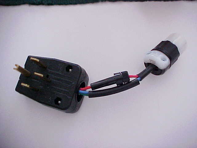
Household 240V service comes from a step-down transformer at the street. The incoming line voltage is 240V to the main panel, separated into two poles ("hots") and a neutral. At the main panel, neutral is tied to ground, as in a grounding rod or clamp to a buried metal pipe. The voltage from each pole to the neutral is 120V. The voltage across the two poles is 240V. At the breaker panel, the bus bars are arranged so that a big breaker can cross the two poles (a double-pole breaker, 240V) or a smaller breaker can just connect to one (a single-pole breaker, 120V). In the plug, I connected the fuse holder to one of the "hot" prongs , the neutral prong to the neutral from the 5-15 receptacle, and ground to ground. In the 5-15, I connected the smaller "hot" blade to the line from the fuse holder, and connected the neutral and ground. That produced 120V at the receptacle, and gave me the right voltage to run the stove. Note that this DOES NOT work with a 3-bladed stove receptacle, as there is no neutral in that setup.
I whipped up an adapter that plugged into the 240V/40A range plug behind the stove. It consists of a NEMA 14-50 plug, a NEMA 5-15 (common household plug), a couple strands of 14 gauge wire (rated to handle up to 15 Amps), and a fuse holder with a 15A slow-blow fuse. For those who don't know, the NEMA numbers stand for the configuration of the prongs on the plug or receptacle and are specific to each voltage/amperage combination.
The proper way to solve this issue is to rewire the receptacle. For three wire range plugs, change the breaker in the panel from a double pole to a single pole of the correct amperage, and reuse one of the hot lines as a neutral. For a four wire installation, cap the extra hot wire on both ends. Be sure to use a 110V receptacle rated for aluminum wire if it is present.
This modification didn't last long for me. With the installation of the hot tub some months later, I was forced to reuse the breaker spot in the panel for the tub, and tapped off an existing 120V line to run a new receptacle behind the stove that I installed.
Hot Tub Electrical Wiring
The proper term is "portable spa", but I call a tub full of hot water a hot tub.
Hot tubs electrically fall into three categories: 120V (often convertible to 240V), 120/240V, and 240V only. My particular spa is a 120/240V, with the motors and heater being 240V, and the light and ozonator running on 120V. 240V operation is desirable, as the motors will laster longer and the heater is more efficient and powerful. The 120V only spas will shut off the heater while the motors are running. The water and air jets drain the heat from the water quickly.
Tubs can draw a LOT of current. My particular tub has a GFCI breaker in the spa pack (the controller) which indicates up to 40 amps. Because of the electricity and water combination, tubs require some very careful wiring. The wire must be rated to handle the current load, a GFCI breaker is required in the circuit, and an emergency cutoff switch must be installed no farther than 15 feet and no closer than 5 feet to the tub. In addition, code required a bonding wire (really just another ground) of at least 8 gauge to be run from the panel to the tub. Check your local and national electrical code.
For my dual-voltage installation, a three-wire with ground bundle plus the bonding wire was required. A look at the wire gauge ratings shows that 50 amp circuits using copper wire require a 6 gauge conductor. Don't bother with aluminum wire. Aluminum requires a thicker wire to handle the same current capacity, and is not compatible with all terminals. These days, aluminum is only used for large circuits or feeders with appropriate termination.
I installed a 50 amp GFCI breaker in the panel. The breaker has different terminals than regular breakers. There are terminals for the two hot wires, a terminal for the neutral out, and a neutral pigtail that connects to the neutral bus in the panel. This breaker costs about $90, but is well worth it. Even if your spa pack has a GFCI breaker in it, install one in the panel or sub-panel that feeds the tub. It's more durable than the units put in most spas.
From the panel, I ran 6 gauge 3 conductor wire with a 10 gauge ground and the separate bonding wire out to the deck, where I installed the emergency cut-off. At the point that the wire leaves the house, use grey ultraviolet-resistant PVC conduit to protect your wire (once again, check your local codes on this; they may want metallic conduit). You need not use conduit for the bonding wire. The cutoff is a spring-assisted unit rated up to 60 amps made by Siemens. Non-fused air conditioner disconnects will also work and go for under $10. At the disconnect, I stripped a section of the sheathing from the wire bundle and cut the two hots and the included ground to connect to the appropriate terminals in the box. I left the neutral uncut. The neutral should never connect to anything except the tub terminals and the breaker in the panel; otherwise, the GFCI will see that some current is not returning (since it's traveling back to the panel through the ground wire or other path) and trip constantly. The ground wire should be used to ground the disconnect switch box but need not be continuous to the tub since the extra bonding wire is run. I connected it through anyway. At the tub, I connected the bonding wire to the ground terminal and the hots and neutral to the appropriate terminals. Since these connections are subject to corrosion due to their environment, use a little dielectric grease to keep them shiny.
Repairing a PVC drain fitting
The moral of the story: never install plumbing in an outside wall.
During the course of installing the wiring for the hot tub, I noticed that I had a wet spot near one of the PVC pipes in the crawlspace. Further inspection showed a gash in the side of the pipe with a hole about 1/2 inches across. At first, I thought that a rat had been sharpening his teeth on the pipe, but closer inspection showed otherwise. When the deck was bolted to the back of the house, holes were drilled through the band for large bolts. The moron that installed this deck drilled into the pipe, realized his mistake and redrilled the hole about 2" away. The house was built in 1997, so this drain had been open for 5 years by the time I found it. This particular pipe was 3 inches across and served as the drain riser for all of the second floor!
I repaired the gash on the side of the pipe, but noticed on re-inspection that water was still slowly dripping from parts unknown. It was apparent that the water was coming from elsewhere and I needed to remove the fitting to find the breach. Because of space limitations, if I simply cut the fitting off, I would not be left with enough pipe to attach a new elbow. This meant I would have to open the wall and splice in a longer piece of pipe. That's a lot more work than I wanted to do.
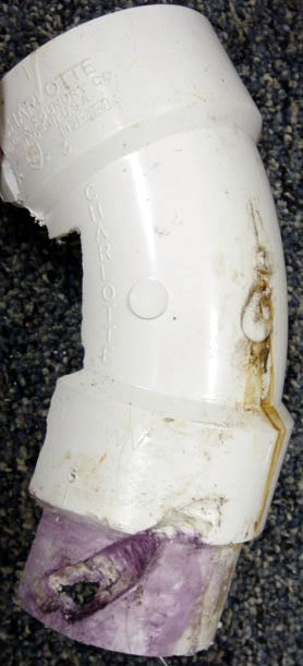
I used a Dremel with a side-cutting bit and a narrow wood chisel to cut the upper flare of the fitting. Working carefully, I split the fitting without damaging the pipe inside it. Once the fitting was split, I used the chisel and a small prybar to crack the solvent weld all the way around the pipe, and removed the entire fitting. As it turns out, there was also a flashing nail penetrating the back of the elbow. This was the actual source of most of the water.
In these pictures, the nail hole at the back of the elbow fitting is clearly shown. The lower section shows the pipe with a gash that is a perfect representation of the auger that hit it. The proximity of such a large pipe to so many fasteners (siding, flashing, and deck bolts) is a good reason to always run your large drain pipes inside interior walls.
Troubleshooting non-operational air conditioning
So it's just about the start of the hot summer here in North Carolina, and my air conditioner started blowing lukewarm air overnight.
The first contractor that could come out was quoting one week before they could get to us. Our house was on the market, and I knew that if anyone noticed that the upstairs was 85 degrees (how could you not?!?), then they would not be interested in the least. I decided that I'd see if I could fix this thing myself.
Our second floor unit is a split system, where the blower control circuitry are inside and the compressor, fan, and coils are outside by the house. The outside unit components were not running, so that's where I started.
Here are the things I checked:
- Reset circuit breakers at the panel and check outside disconnect. OK
- With disconnect out, check all terminals for good connection. OK
- With disconnect out, check fan motor for binding when turned by hand. OK
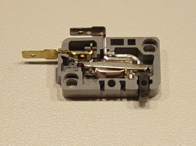
- With disconnect out, activate thermostat to check the contactor relay. Voltage from the control circuit should be 24VAC. OK
- Disconnect everything from contactor output terminals. With breaker on and disconnect in, check line voltage across input terminals of contactor for 240VAC. Repeat for output terminals. OK
- Check run capacitor (big silver can with three terminals) capacitance. Obviously, this is hard to do without the correct equipment, but look for bulging of the case or oil leakage. NOT OK!
The run capacitor top was domed up, which is easy to miss unless you know that they are supposed to be flat!
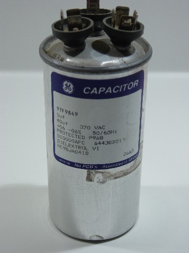 If you aren't familiar with run capacitors, don't sweat it (ha-ha). Just know that for most efficient operation, a run cap with the correct capacitance values (expressed in microfarads, abbreviated on labels and boxes as "uF" or "mfd") must be installed. There are three contacts because there is one value for the fan and another for the compressor. You can replace the cap with one that shows the same two values (mine was 40.0/5.0 or "40+5"). They come in two voltage ratings and shapes for residential use - 370V or 440V, round or oval canister. You CAN use a higher voltage rating capacitor, but never a lower one. And as you would expect, shape doesn't matter either. Just be aware that changing voltage or shape means you will probably have to make your own mounting bracket.
In my case, I used a 440V cap, because the service company I bought it from didn't stock both. I purchased it directly at their office for $32.10. The box was marked $70, because that's what they charge you for it off the truck, plus labor and any other service charges. Since it was physically larger, I drilled a new mounting hole (carefully, don't drill into the coils!) and used a hose clamp screwed to the mounting point as a bracket.
I found this site more than a little helpful in diagnosing my problem. I contacted them afterwards to thank them for posting so much information, and they are genuinely nice people.
Burnt out CATV service line
This one took a bit of time to solve. If a search engine brought you here, read quickly and then grab the phone!
I got a call from my fiancee around noon one summer Wednesday, complaining that the cable Internet service (and therefore the Vonage service) was down. Not only that, but the TVs were offline too, which told me that this was not a brief network disruption. I got home around 4pm and stopped by the service entrance at the side of the house. About six inches of the service provider's end of the cable to the grounding block was completely melted. The insides of the grounding block were also melted, allowing the center conductor to touch the shield, which took out the service. I cut back the bad parts and put new ends on, since Time-Warner said it would take them two days to have a technician onsite (unacceptable!)
This was the second time in a year that the service had failed exactly this way. The first was also a hot summer day. The technician that responded said it looked like a lightning strike, and promptly fixed the problem. I checked the connections to the service ground near the meter base and the clamp on the house ground rod. The clamp at the ground rod was loose, so I tightened it and assumed the problem was fixed. Your service ground may be tied to a grounding rod like mine, or to a metallic water pipe if you have one.
On Saturday, the cable problem continued to spook me, so I retrieved my brand-new current clamp from All Electronics, a great site for random electronics hobby stuff, and put it on the incoming cable service line from the street. The reading was about 4 amps! The 12 gauge wire from the grounding block showed the same, as did the length of grounding wire from the connecting point into the meter base. The service ground read 0.2 amps, and the cable feed into the house read 0. As I monitored it, that 4 amps briefly became almost 10!
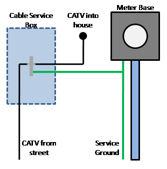 At that point, it was apparent to me that I had a faulty neutral - return current from my electrical service was being partially shunted to the CATV coax! When the return current exceeded what the foil shield of the cable could handle, it melted. The service ground was a higher impedance than the path to the CATV system, so only part of the shunted current was returning to Earth as it was designed.
Note that this is how the National Electric Code intends for the service ground to work, so don't think that unplugging your grounding block's ground connection will help. Many CATV coax connected devices ground the shield of the coax, including the splitters commonly used in whole-house structured wiring boxes. Without a ground at the service entrance, it is likely that another CATV connected device inside your house will be the next best return path, bringing potentially damaging current and the possibility of fire inside your walls - this is a Bad Thingtm! This also holds true in the case of lightning and other electrical surges.
I put in a call to my local power service company and informed them that I had an open neutral. I described the symptoms: melted cable and devices in the house flickering when I unplugged the cable service. They dispatched a technician who opened the meter base and found a loose neutral terminal. If you are there during the service, make sure they check the terminal lugs for cracks, too.
My theory is that when the weather got hot, the poor neutral connection opened up just enough to put more current down the CATV and melt it. Once the coax was melted, the current was shunted non-destructively to Earth.
None of this is intended to be a definitive repair course. Rather, this shows that with a little knowledge, you can approach what is a daunting problem better prepared. Having this knowledge allows you to speak more intelligently with contractors that you might employ to fix the problem and help you recognize if you are being mislead. If the problem isn't too bad, you can even fix it yourself.
Back to Toby's Home Page